If you have been making too many dry solder joints, then here are some tip on soldering. By the way, just in case you did not know, dry solder joints can create a potential fire hazard, add unnecessary noise in the circuit and add to instability of electronic circuits. Hence some quick and dirty tips:
1. Make sure that you are using the right soldering iron for the job. You need to have enough wattage to thoroughly heat the parts without burning them out. For example, while a 15 watt soldering iron is good enough for soldering tiny microprocessors on a printed circuit board (PCB), it would not work if you are planning to solder 10 AWG stranded wire speaker connection on a crossover network. For that you will need at least a 60 watt soldering iron. By the way, there are variable wattage soldering irons available too.
2. There are rosin core and acid core solder availble in the market. Rosin core solder are used for all electronic work. Don't ever use acid core solder for electronic work.
3. Flux is used to avoid oxidation of exposed copper during soldering of electronic circuits. I like to use liquid flux with a tiny brush. I have used flux paste too but my preference is still liquid flux.
4. It is a good idea to "tin" the tip of the soldering iron (unless you are using a nickle/chrome plated soldering tip). Tinning of parts is also a good idea. This avoids oxidation build-up and improve the quality of soldering by improving heat transfer.
5. Unless you are using a nickle/chrome plated soldering tip, you should file the tip of the soldering iron to remove oxidation build-up.
6. Heat the tips of the parts that you are trying to solder by quickly touching them with the tip of the soldering iron before applying the solder. Apply the solder, when all the parts are hot. The melted solder will flow evenly coating all the surfaces.
These tips will help you make a good electrical connection. All the best!
Sunday, November 15, 2009
Sunday, October 25, 2009
Building a Multimedia Server: Remote Infrared Control
Gentlemen and occasional ladies, here is the second volume of Multimedia Server series of blogs. This covers remote infrared control of audio receivers and other home entertainment equipment. Infrared continues to be the standard for remote control of home electronics and entertainment equipments. It has two severe flaws:
- No talk back or acknowledgment capability
- Line-of-sight remote control
Infrared remote controls, per se, do not expect to receive an acknowledgment of the command that they send to home entertainment equipment. In a complimentary fashion, home entertainment equipments do not care to send an acknowledgment to the infrared control that the command that was issued has been executed. This situation is like a deaf and blind person giving a command to a dumb and blind person. Both of them are blissfully unaware of the real status of each other. This is not a real problem when home electronics equipments are in the line-of-sight, since you can view the status of the equipment directly. However, this becomes a real problem when you have to hide all that home entertainment equipment in an old shelf in your basement, garage or attic.
Let us first solve the problem of "line-of-sight". A couple of years back, there were tons of complicated solutions that required installation of expensive infrared distribution hubs and wiring. Now this issue has been resolved by several manufacturers in innovative ways. These devices are called remote control extenders. Here is how I have quickly classified them:
- Type 1: Universal Remote Control and several other remote control manufacturers make remote controls that generate UHF signal in addition to infrared signal. In addition, they make a base station that converts UHF signal back to infrared signals. Unlike infrared (IR) signal, UHF signal is not blocked by walls.
- Type 2: Powermid type of signal converters, which receive the IR signal and convert that signal to the RF signal. At the other end, a Powermid receiver receives the RF signal and converts that back to the IR signal.
- Type 3: X10 infrared signal receivers, which receive the IR signal and convert that into an X10 signal, which you can use to control and X10 power control device to turn the equipment on and off.
- Type 4: Insteon infrared receiver and transmitter devices that can receive infrared signals and convert them to Insteon signals and vice-versa.
There are several other solutions like z-wave and more expensive professional-grade IR distribution systems. I briefly looked into these other systems and dropped them from my list since either they were too expensive or I was unwilling to spend time to learn an unfamiliar technology.
Type 1 Non-line-of-sight Infrared Remote Control Solutions
I use a URC (Universal Remote Control) MX600 remote control with MRF-250 base station. 

 You can find more details on these on www.universalremote.com website. This remote control takes a little getting "used to" but give it a little time and I can assure that you will begin to love it. You will need to use IR emitters (with 2.5mm mono male plugs, if you are using MRF-250 or you will need 3.5mm mono male to 2.5mm mono male adapter, if you are using IR emitters with 3.5mm mono male plug), since IR blaster generally causes an overload of IR signal, if it is too close to the audio equipment.
 Since I have MRF-250 too close to my audio equipments, I found it quite unreliable. Therefore, I've used IR emitters all over. I recommend using triple head (or 3-eye) IR emitters, which will allow you to remote control up to 18 different devices, for instance, satellite receiver, 300-DVD jukebox, audio receiver, subwoofer amplifier, etc
Type 2 Non-line-of-sight Infrared Remote Control Solutions
I liked X10 Powermid device for converting IR signals into RF signals. 
You can find a lot more details about this device on www.smarthome.com. However, I did not like pointing my remote all the time at this device. Secondly, this pyramid shaped device was breaking the décor of the family room. Therefore, I decided not to use it. Here is a stock picture of Powermid remote control extender device.
If you are already using X10 protocol for home automation, I understand that Powermid will allow you to convert IR signals to X10 signals over home power line. I haven't tested this feature though.


"Next Generation" Remote control extender is conceptually similar to Powermid. However, the "Next Generation's" transmitter in this case is hidden in the battery compartment of your remote control. It cleverly replaces one of the 1.5volt AAA or AA batteries in the battery compartment of your remote control with a half-size rechargeable battery of 1.2volt and uses the remaining space to insert a tiny RF transmitter. The half-size rechargeable battery and the RF transmitter are in an AAA sized sleeve. For AA size batteries, you insert AAA-sized RF transmitter sleeve into another AA-sized sleeve. This remote control extender seems to be quite popular on www.amazon.com with more than 500 positive reviews. The best benefit is that you can continue to use your existing remote. However, I came across two major issues with this remote control extender. These are as follows:
- The spaceship shaped RF receiver that converts RF signal back to IR signals has only one 3.5mm IR emitter jack behind it. Therefore, if you are planning to use IR emitters, you can't control more than six devices. The reason is that the most eyes IR emitters have are six. I tried a 3-eye IR emitter and it was quite effective. I did not try 6-eye IR emitter.
- Each remote control unit will need a transmitter and a rechargeable battery. If you have used a "learning remote control" to transfer all the IR commands for various home entertainment devices to a single remote control then that solves this problem. However, I found that rechargeable batteries had to be charged frequently. The battery charger is in the spaceship shaped receiver. Therefore, if your home entertainment devices are located in your basement, you will have to go there each time you needed to replace the rechargeable battery.
Type 3 Non-line-of-sight Infrared Remote Control Solutions
 These are X10 infrared receivers that receive an IR signal and convert the IR signal into an X10 signal. Now you can use other X10 devices, e.g., X10 appliance module, to control your remote home entertainment center. The problem is that your remote control will be limited to the controls allowed by X10 hardware. In addition, X10 is not a reliable protocol for communication, since similar to IR remote controls, it does not send an acknowledgment. On the other hand, the benefit is its low cost of ownership. I tested X10 model IR543, which can control four X10 modules. In general, I'd not recommend it for controlling power to your home entertainment devices.
Type 4 Non-line-of-sight Infrared Remote Control Solutions
 These are powerline+RF communication devices that send an acknowledgment. One of the protocols developed by SmartHome (www.smarthome.com) is Insteon. For instance, SimpleHomeNet's EZUIRT can work as an IR distribution hub. You will need two of these transreceivers. One to convert IR signal to Insteon signal and another one to convert Insteon signal back to IR signal. Alternatively, you an use IRLinc to convert IR signals to Insteon and then use EZUIRT to convert Insteon signals back to IR. I'm using an IRLinc to dim lights while watching movies using the same remote control that I use to control the multimedia server and home entertainment devices. Perty cool, eh!
Solving the Problem of Lack of Acknowledgment
 This requires using an acknowledgment based reliable communication protocol to supplement IR signals. The way I have done it is that I've used Insteon-based low voltage input/output control modules (e.g., I/O Linc) to send a signal to a KeyPadLinc button, when a device is turned on or off. Therefore, when I turn-on my multimedia server controller (Helios, now discontinued and manufacturer closed down) using my UHF remote control MX600, Helios sends a signal to SimpleHomeNet's EZIO Input/Output relay controller through a 110v to 6v 100ma DC step down transformer. EZIO sends a corresponding Insteon signal to KeyPadLinc device in my family room, which lights up the LED under that button confirming to me that multimedia server controller is turned on. Please refer to SmartHome website for more details on Insteon-based home automation modules.
Some of the newer models of audio receivers now have TV output of status, e.g., volume control, channel select, etc through HDMI output. This is another way of solving the problem of lack of acknowledgment. I found it best to use a combination of methods to achieve the degree of control that best suits your needs.
Finally, a couple of words about remote control of the desktop PC that works as my multimedia server. I have discussed this topic in more detail in my earlier blog on infrared control of a ReadyNas device. I'm providing a link here. Therefore, I'd skip this topic. I've used the same method to soft-on and soft-off my desktop PC using infrared remote control. Basically, what I've done is that I've added an infrared controlled power switch in parallel to the existing push button switch that turned-on and turned-off my desktop PC. Let me confess that I tried the PC remote control devices and USB IR receivers as shown below in pictures but decided to give them up due to following reasons:
- I found that the software had spyware built-in
- USB ports do not have standby power, therefore when desktop PC is turned-off, I can't turn it on using USB IR receiver
 I have included a brief description of these USB IR receiver-based PC remote control devices because you never know, what did not work for me may work for someone else.
 In my next blog, I'll be discussing the setup and configuration of multimedia controller and server.
Monday, September 7, 2009
Reovering Data from Hard Drive Failure
Well, this last Friday I was working on a circuit design on my laptop, when I had to step out for a moment. I closed my laptop. In about an hour when I opened the laptop, there was a message on the dark laptop screen: No hard drive detected!  I turned off my laptop, rebooted and heard a squeaking and screeching sound from the hard drive. Finally after a couple of minutes my laptop displayed the same message. Well, this "was" a Seagate Momentus 2.5" 5400.4 250 GB SATA internal hard drive (for laptops) that I had purchased just about two months back!
I had recently started working on a circuit design for an attenuator and I was a bit shocked that I was going to lose all the design work that I had accomplished in the last six weeks.
I have a SATA internal hard drive docking station. I pulled out this Seagate drive from my laptop and inserted it in the docking station. All I heard was more of the same sound. When I paid close attention to the sound, I could discern that spindle was trying to spin but something was stopping it from spinning. What could it be? After carefully listening to the sound for some time, I was sure that the head had crashed on the platter and the platter was unable to spin. There were all the tell tale signs. Laptop was unable to recognize the drive, which basically meant that either lack of spinning or dead electronics. However, dead electronics does not create a sound like someone trying to spin but can't.
 So I accepted the loss of my hard work with a feeling of resignation and decided to get the drive replaced from Seagate. Meanwhile, I bought another 320 GB Hitachi Travelstar 2.5" laptop internal hard drive.
  Hitachi Travelstar box had a picture of an exposed internal hard drive showing the actuator arm, head and the platter. When I opened the box, there was a red colored brochure that had another actual sized picture of an internal hard drive without cover showing all the internal mechanical details of a laptop hard drive.
 After all, inspiration for all things stupid comes from somewhere. In my case, the inspiration came from the picture on Hitachi Travelstar box. Looking at the picture, I had this stupid inspiration of trying to repair the hard drive by opening it. It really seems kind of retarded but due to some reason I have liked the feeling of having a screwdriver in my hand to take apart things that are working or not working. I knew that I was going to kill the warranty if I opened it. On the other hand if I fixed it I would save about six weeks of work.
Well, I've been around Intel and I've seen assembly of electronic components. Those are ultra clean environments called Class 100 clean environments. Employees wear gloves and caps like surgeons. My den is hardly a Class 100 clean environment. But it was worth a risk.
It is easy to open Seagate Momentus 5400.4 internal hard drive for laptops. All you need is a Torx T-7 screwdriver. There are six screws on the periphery and the last screw is actually below the plastic sticker and it is covered by a shiny metallic film to maintain warranty. I opened some of the screws and took a peak inside.
  My hypothesis was right. I saw that the head was stuck on the platter.
  Normally, in a powered down state, the head should be off the platter in its parking spot. Though I know that there are some hard drives that don't follow this rule, Seagate Momentus 5400.4 is not one of them.
Since I did not have a Class 100 clean environment, whatever I had to do after opening the drive had to be done quickly. I donned my vinyl gloves and cut a tiny paper loop using a premium glossy paper. After opening the drive, I gingerly threaded the paper loop around the actuator arm and pulled it back to its parking spot. It was really stuck on the platter (stiction), since it made a clicking sound when I unstuck it and pulled it to its parking spot.
  When I was about to close it I noticed a tiny particle on the platter. I removed it carefully with my vinyl covered fingers and put the cover back on.
  Since I did it quickly, you will notice that I did not take any pictures of the open Seagate drive. I have used paper cut-outs from Hitachi Travelstar box and the brochure to show you how I did it.
After that I put the Seagate drive in the SATA docking station, connected the USB from docking station to another laptop, prayed to the Almighty and powered on the docking station. Possibly my prayers were successful. I could hear the sound of platter spinning and the drive was recognized by the laptop. I knew that I had just a couple of hours before the drive was going to die again. I copied all my files. I found that some of the files had got corrupted and could not be copied but I was able to get about 90% of what I wanted. After I had copied most of the stuff that I needed, the drive died again.
Well, this was just a couple of hours of nerdy fun on an otherwise languid Friday. I don't know if this method of hard drive data recovery would work for others or not. Whether it works or not, it surely will kill warranty. Do it at your own risk!
Note: I had requested a quote for recovering data from my failed hard drive. The quote arrived today in my e-mail. The fixed cost of recovering data from my hard drive is quoted at $650. This is a reputable company and I think its a reasonable price. I understand that cost of data recovery by I365 is in the range of $1200 but it is hard to pin down a price due to so many variations in data recovery issues.
 I turned off my laptop, rebooted and heard a squeaking and screeching sound from the hard drive. Finally after a couple of minutes my laptop displayed the same message. Well, this "was" a Seagate Momentus 2.5" 5400.4 250 GB SATA internal hard drive (for laptops) that I had purchased just about two months back!
I had recently started working on a circuit design for an attenuator and I was a bit shocked that I was going to lose all the design work that I had accomplished in the last six weeks.
I have a SATA internal hard drive docking station. I pulled out this Seagate drive from my laptop and inserted it in the docking station. All I heard was more of the same sound. When I paid close attention to the sound, I could discern that spindle was trying to spin but something was stopping it from spinning. What could it be? After carefully listening to the sound for some time, I was sure that the head had crashed on the platter and the platter was unable to spin. There were all the tell tale signs. Laptop was unable to recognize the drive, which basically meant that either lack of spinning or dead electronics. However, dead electronics does not create a sound like someone trying to spin but can't.
 So I accepted the loss of my hard work with a feeling of resignation and decided to get the drive replaced from Seagate. Meanwhile, I bought another 320 GB Hitachi Travelstar 2.5" laptop internal hard drive.
  Hitachi Travelstar box had a picture of an exposed internal hard drive showing the actuator arm, head and the platter. When I opened the box, there was a red colored brochure that had another actual sized picture of an internal hard drive without cover showing all the internal mechanical details of a laptop hard drive.
 After all, inspiration for all things stupid comes from somewhere. In my case, the inspiration came from the picture on Hitachi Travelstar box. Looking at the picture, I had this stupid inspiration of trying to repair the hard drive by opening it. It really seems kind of retarded but due to some reason I have liked the feeling of having a screwdriver in my hand to take apart things that are working or not working. I knew that I was going to kill the warranty if I opened it. On the other hand if I fixed it I would save about six weeks of work.
Well, I've been around Intel and I've seen assembly of electronic components. Those are ultra clean environments called Class 100 clean environments. Employees wear gloves and caps like surgeons. My den is hardly a Class 100 clean environment. But it was worth a risk.
It is easy to open Seagate Momentus 5400.4 internal hard drive for laptops.
 All you need is a Torx T-7 screwdriver. There are six screws on the periphery and the last screw is actually below the plastic sticker and it is covered by a shiny metallic film to maintain warranty. I opened some of the screws and took a peak inside.
  My hypothesis was right. I saw that the head was stuck on the platter.
  Normally, in a powered down state, the head should be off the platter in its parking spot. Though I know that there are some hard drives that don't follow this rule, Seagate Momentus 5400.4 is not one of them.
Since I did not have a Class 100 clean environment, whatever I had to do after opening the drive had to be done quickly. I donned my vinyl gloves and cut a tiny paper loop using a premium glossy paper.
 After opening the drive, I gingerly threaded the paper loop around the actuator arm and pulled it back to its parking spot. It was really stuck on the platter (stiction), since it made a clicking sound when I unstuck it and pulled it to its parking spot.
  When I was about to close it I noticed a tiny particle on the platter. I removed it carefully with my vinyl covered fingers and put the cover back on.
  Since I did it quickly, you will notice that I did not take any pictures of the open Seagate drive. I have used paper cut-outs from Hitachi Travelstar box and the brochure to show you how I did it.
After that I put the Seagate drive in the SATA docking station, connected the USB from docking station to another laptop, prayed to the Almighty and powered on the docking station. Possibly my prayers were successful. I could hear the sound of platter spinning and the drive was recognized by the laptop. I knew that I had just a couple of hours before the drive was going to die again. I copied all my files. I found that some of the files had got corrupted and could not be copied but I was able to get about 90% of what I wanted. After I had copied most of the stuff that I needed, the drive died again.
Well, this was just a couple of hours of nerdy fun on an otherwise languid Friday. I don't know if this method of hard drive data recovery would work for others or not. Whether it works or not, it surely will kill warranty. Do it at your own risk!
Note: I had requested a quote for recovering data from my failed hard drive. The quote arrived today in my e-mail. The fixed cost of recovering data from my hard drive is quoted at $650. This is a reputable company and I think its a reasonable price. I understand that cost of data recovery by I365 is in the range of $1200 but it is hard to pin down a price due to so many variations in data recovery issues.
Saturday, August 29, 2009
Building a Multimedia Server: Remote Power Management
I'm sure that most of the music aficionados are well aware of SAF effect. This is how spouse acceptance factor effect comes into play. You have searched around and around for a receiver with a great musical output. You drilled into its electronics, figured out that discrete components with MOSFETs, huge toroidal power transformer and even bigger capacitors were producing a better sound. Then you found a set of seven speakers that provided the sonorous sound that you were looking for and as your search for a perfect and affordable music system reached its denouement, you finally found a coffee table sized sub-woofer that gave a solid punch to 0-100 Hz range. Sorry, we reached the denouement too early. As you hook up all the systems in your family room and and start enjoying the music, your spouse walks in and he or she is horrified beyond belief at the sight of this new shrine that was earlier his or her family room now dedicated to your ultimate music systems.
Our goal is to figure out how we deal with this SAF effect. There is an easy way. Move all the receivers, subwoofer amplifers, 300-DVD and 300-CD jukeboxes, multimedia server, surge protectors, etc. in another room in the basement, garage, unused hidden shelf that your spouse does not care about or attic, if you have found out a way to keep attic temperature under 95 degree Fahrenheit.
There are a few little problems with this approach though. First of all, how do you control all the infrared remote controlled home electronics equipment, when it is not in the line of sight. Secondly, how do you get system status. Ideally, I'd have liked to have a two-way Bluetooth remote control that would not only send a command but also receive return status from each multimedia equipment and display it. Nobody has yet made such a Bluetooth remote control. This is a multi-million dollar idea, which I'm giving away for free. Now, we will have to figure out a cheaper way of remote controlling our home electronics.
Let us start with the control of power. Our goal is to be able to soft turn-on and soft turn-off a multimedia server PC and then use that to turn-on/turn-off rest of the dependent equipment, for instance, receiver, 300-DVD or 300-CD jukebox, subwoofer amplifier, et cetera. We will talk more about remote IR control later. Let us discuss about power first. Those of us who are hardcore may probably look for remote control power devices like Baytech RPC-3 and RPC-4. In fact, Monster--the guys who figured out how to make money selling cables--are now making some real expensive devices for remote management of power for home electronics. For instance, Monster Signature Series HTPS 7000 MKII is one such power management system. Monster also makes Empowered series of PowerCenters with out of sight infrared control of each power port using an external infrared receiver and a bunch of infrared emitters. These devices are Empowered PowerCenter EP3650 and EP2450. Empowered series PowerCenters do not have relay controlled switched power ports. Signature series HTPS 7000 MKII has switched and unswitched outlets similar to HTS 1000 MKIII. However, I have yet to find a device that has all of the following features:
1. Discrete (not toggle) infrared control for each power output port - This means that an on means on, and off means off no matter how many times you press the same button on your remote
2. Surge protection and power filtering
3. Current sensing Master/slave power control with current-sensing sensitivity control
4. Individual relay controlled or relay triggered power ports
5. If-then-else programmable power ports
6. Computer connectivity and ability to check and control through a computer
7. Remote talk-back status (or acknowledgment) capability
8. Possibly, ability to program delays in turn-on and turn-off of some power ports. For example, when multimedia server PC is turned on, you may want external disks to be turned on right away but depending upon boot up time, you may want to delay receiver/amplifier turn on to be delayed by 30 seconds. Similarly, when multimedia server PC is turned off, you would want external hard disks to be turned off a couple of seconds later.
Therefore, for my purposes even the best in class Signature series power control device like HTPS 7000 MKII is not enough. For example, it would not make much sense to put a multimedia server PC, multiple external hard disks, analog-to-digital converter dongles, HDMI switchers on HTPS 7000 MKII.
If we can't find one power management device that will meet all our needs, the only alternative is to find a couple of devices and hook them up in a configuration that will hopefully meet our needs. Let us start with current sensing power switches. What we are looking for is a switch that senses that one of the equipments connected to its master control has been turned on and turns on the slave power. These are simple current sensing power switches. These current sensing master/slave switches are often used in tool shops. For example, if you turn on a saw, you may want to turn on a vacuum cleaner to suck up the dust.
Below are some recommendations but only first three are current sensing. Others have relay triggers, computer control and talk back capabilities.
1. Smart Strip Power Strips marketed by Bits Ltd.
2. Craftsman Auto Switch sold by Sears
3. DGC i-Socket
4. Monster Home Theatre PowerCenter HTS 1000 MKII
5. Baytech RPC3 or RPC4
6. Niles AC-3 Voltage Triggered AC Power Strip
Lets start our discussion with Smart Strip Power Strip. Its cost is in $30 - $50 range depending upon the model that you like. I've shown a picture of LUG4 Smart Strip with a control outlet and USB port. What I liked about it is that it has an adjustment for sensitivity. After designing it the makers realized that there were several teeny-weeny laptops that did not draw enough current to activate switched/slave outlets. Therefore, they decided to add a sensitivity control, which allows you to change the sensitivity (sensitivity to detect small amounts of current or amps) to suite your equipment. The problem is that if you set the sensitivity too low and your PC draws tiny amounts of current in quiescent state, then the rest of the equipment on the slave/switched outlet will not turn off. But you control sensitivity, therefore, you can change it. There is one more benefit.
  LUG3 and LUG4 models of Smart Strip have a Type B USB connector or receptacle. You can connect this USB receptacle to your PC's Type A USB port using a standard USB AB cable. USB ports provision 5 volts, which is enough to activate a relay. Therefore, as soon as you turn on your multmedia server PC, this USB port on Smart Strip will detect that the multimedia server is turned on and turn on rest of the equipment connected to switched outlets. If you are using control outlet as well as the USB port on Smart Strip, then the Smart Strip will turn on switched outlets if either of these is turned on. The Smart Strip will turn off switched outlets only when both control outlet and USB port are turned off. Since receivers and amplifiers draw tons of current, I would be careful about using too many outlets on this strip. You certainly don't want to create an overload situation. You may want to check its manual to find the maximum wattage.
Craftsman Auto Switch sells for a penny under $20. It has just the right level of sensitivity that as soon as it detects that multimedia server PC is turned off, it turns off the other two switched slave outlets. On the Sears website you will notice that this auto switch has received lots of positive reviews.
Next in line is the review of DGC i-socket 110m. I noticed that this one has one or two possibly minor issues. First of all there is no sensitivity control. Secondly, it will not detect the load on "Tool", which is the master or control outlet unless the draw of current on the control/master outlet exceeds about 0.5 amps. In other words the load on master outlet has to be higher than 55 watts in order for the switched outlet called (VAC on i-socket) to be turned on. However, there is one feature that I really liked about it. After the equipment on the control/master outlet is turned off, it waits about 7 seconds before turning off the slave switched outlet. This is one heck of a great feature. For example, if you have your multimedia server PC running on the control/master outlet and external hard drives running on the slave/switched outlets, then after you turn off your multimedia server PC, the disks will have plenty of time to go quiescent before being powered off. This will substantially reduce chances of disk failure.
I was a little bit dismayed by low sensitivity level of DGC i-socket. Therefore, I disassembled it to understand what was going on. I had a mixed reaction after reviewing its design. On the positive side I noticed that it used an Atmel ATtiny13 microcontroller for controlling the circuit. This software-based control clearly provides a lot of flexibility. On the other hand, I was disappointed that it was not using opto-isolators. It uses a current sensing transformer in the dual role of current sensing and circuit isolation. It uses a solid state relay (Triac) BTA-24, which is quite fast and if I recall correctly this triac can safely handle current output of 15 amps. In fact, it is rated for much higher.
Though, I have not measured it but it is likely that these devices introduce tiny bits of distortion or phase-shift in the current that passes through their electronics. Though I have not noticed it but I cannot discount the possibility that this distortion could become noticeable if you cranked-up your receiver/amplifier volume. I think this is what has provided Monster an entry into building and marketing high-end power supplies. Though CFL bulbs, refrigerators and other equipment can also distort theoretical power characteristics, I've never noticed such power distortions in the sound output. Perhaps my ears are not sensitive enough. But I'm unwilling to spend $1200 to buy an audio power filter dedicated to my receiver/amplifier.
But if you are one of those purists who spend $200 to buy audio cables, then there is an alternative. You could use the switched/slave outlets on these master/slave current sensing devices to power up a 3V 50ma (3 volt 50 milliampere or higher but you don't need more than 10 milliampere to activate switched outlets on Monster HTS 1000 MKII) step down power supply/transformer and use that 3v 50ma power to turn on switched outlets on Monster HTS 1000 MKII Home Theatre PowerCenter.
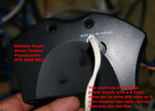 The link that I have given above is actually Monster HTS 1000 MKIII Home Theatre PowerCenter and its manual does not show input for relay activation but the manual says that audio outlets are switched outlets. Therefore, I'm assuming that like its older brother MKII, HTS 1000 MKIII also has an input jack for relay activation of switched outlets. Since I own a couple of MKIIs, I can confirm that MKII series does have a 3.5mm female jack for relay activation.
  You will need to make sure that the low voltage power supply that you use have a 3.5mm mono male pin at the other end. In fact, I have several cell phone chargers in my electronics junk box. I connected a 3.5mm pin to one of those cell phone chargers to activate the relay on Monster HTS 1000 MKII power strip.
There are several receivers, which have 3.5mm relay control (or triggers) output jacks at the back. These relay control outputs can be programmed through the receiver to turn on or turn off HTS 1000 MKII power strip. All you have to do is to get a 3.5mm mono male pin to 3.5mm mono male pin (Please note that 3.5mm stereo will have three wires and one of them will be redundant, therefore you just need a 3.5mm mono cable.) cable to connect the relay control jack in your receiver to the 3.5mm input jack of HTS 1000 MKII. Now depending upon how you have programmed your receiver, when you select DVD on your receiver, the receiver will activate DVD relay control (or trigger) and turn on switched power outlets on HTS 1000 MKII.
Our discussion of remote power control will be incomplete without a review of Baytech RPC3 and RPC4 power supplies. RPC3 and RPC4 can be controlled remotely using telnet and a modem terminal respectively.
  You can connect to RPC3 using a telnet session. RPC4 has an RS-232 serial DTE (data transmission equipment) interface. In techy language, this is called out of band power management.
  I've connected RPC4 to COM2 port of multimedia server PC using RJ-45 null modem cable that I prepared. It has RJ-45 connectors on both ends. I use a RJ-45 to DB9 female converter to connect it to COM2 male DB9 port behind the PC.
  I'm running a "COMPort/IP Server" software from Fogsoft (looks like this software company shut its door but there are several other COM port to IP redirection software) that serves one of the COM ports through a telnet session. Therefore, as long as my multimedia server PC is on, my RPC4 has full functionality of RPC3 at half the price.
  I can telnet into the COMPort/IP Server and give commands to the serial port to inquire status of RPC4. As you can notice from the attached screen print, RPC4 provides a lot of functionality as well as metrics for management of power. It shows that the maximum current drawn has been 10.6 amps. In addition, it shows the ambient temperature too. It allows me to check the status and all the critical parameters remotely from any laptop that has access to the network on which multimedia server PC is running. Piece of cake!
AC-3 Voltage Triggered AC Power Strip is a nice little low-voltage triggered device made by Niles Audio Corporation for activating switched power. You can use it to manage up to 1500 watts of power through two switched outlets and one unswitched outlet.
  I'm attaching a stock photo and a diagram that shows how you can use this AC-3 power control device in your home electronics setup. This diagram is available in Niles AC-3 manual.
In my next blog, we will be discussing about infrared remote control, which is the most popular method for home entertainment systems.
At the end of this discussion, we will have a fully functional multimedia entertainment system ready in some hidden location inside your home and you will be able to control it remotely using simple IR commands on your remote control.
Note: There are several other remote power management systems that provide a web interface for management of power. For home multimedia systems, generally, my recommendation is to achieve power control through infrared. You can add talkback and status checking through a home automation control like Insteon or Z-Wave. However, if you are interested in looking further into remote power management using web interface, here are a few leads:
Our goal is to figure out how we deal with this SAF effect. There is an easy way. Move all the receivers, subwoofer amplifers, 300-DVD and 300-CD jukeboxes, multimedia server, surge protectors, etc. in another room in the basement, garage, unused hidden shelf that your spouse does not care about or attic, if you have found out a way to keep attic temperature under 95 degree Fahrenheit.
There are a few little problems with this approach though. First of all, how do you control all the infrared remote controlled home electronics equipment, when it is not in the line of sight. Secondly, how do you get system status. Ideally, I'd have liked to have a two-way Bluetooth remote control that would not only send a command but also receive return status from each multimedia equipment and display it. Nobody has yet made such a Bluetooth remote control. This is a multi-million dollar idea, which I'm giving away for free. Now, we will have to figure out a cheaper way of remote controlling our home electronics.
Let us start with the control of power.
 Our goal is to be able to soft turn-on and soft turn-off a multimedia server PC and then use that to turn-on/turn-off rest of the dependent equipment, for instance, receiver, 300-DVD or 300-CD jukebox, subwoofer amplifier, et cetera. We will talk more about remote IR control later. Let us discuss about power first. Those of us who are hardcore may probably look for remote control power devices like Baytech RPC-3 and RPC-4. In fact, Monster--the guys who figured out how to make money selling cables--are now making some real expensive devices for remote management of power for home electronics. For instance, Monster Signature Series HTPS 7000 MKII is one such power management system. Monster also makes Empowered series of PowerCenters with out of sight infrared control of each power port using an external infrared receiver and a bunch of infrared emitters. These devices are Empowered PowerCenter EP3650 and EP2450. Empowered series PowerCenters do not have relay controlled switched power ports. Signature series HTPS 7000 MKII has switched and unswitched outlets similar to HTS 1000 MKIII. However, I have yet to find a device that has all of the following features:
1. Discrete (not toggle) infrared control for each power output port - This means that an on means on, and off means off no matter how many times you press the same button on your remote
2. Surge protection and power filtering
3. Current sensing Master/slave power control with current-sensing sensitivity control
4. Individual relay controlled or relay triggered power ports
5. If-then-else programmable power ports
6. Computer connectivity and ability to check and control through a computer
7. Remote talk-back status (or acknowledgment) capability
8. Possibly, ability to program delays in turn-on and turn-off of some power ports. For example, when multimedia server PC is turned on, you may want external disks to be turned on right away but depending upon boot up time, you may want to delay receiver/amplifier turn on to be delayed by 30 seconds. Similarly, when multimedia server PC is turned off, you would want external hard disks to be turned off a couple of seconds later.
Therefore, for my purposes even the best in class Signature series power control device like HTPS 7000 MKII is not enough. For example, it would not make much sense to put a multimedia server PC, multiple external hard disks, analog-to-digital converter dongles, HDMI switchers on HTPS 7000 MKII.
If we can't find one power management device that will meet all our needs, the only alternative is to find a couple of devices and hook them up in a configuration that will hopefully meet our needs. Let us start with current sensing power switches. What we are looking for is a switch that senses that one of the equipments connected to its master control has been turned on and turns on the slave power. These are simple current sensing power switches. These current sensing master/slave switches are often used in tool shops. For example, if you turn on a saw, you may want to turn on a vacuum cleaner to suck up the dust.
Below are some recommendations but only first three are current sensing. Others have relay triggers, computer control and talk back capabilities.
1. Smart Strip Power Strips marketed by Bits Ltd.
2. Craftsman Auto Switch sold by Sears
3. DGC i-Socket
4. Monster Home Theatre PowerCenter HTS 1000 MKII
5. Baytech RPC3 or RPC4
6. Niles AC-3 Voltage Triggered AC Power Strip
Lets start our discussion with Smart Strip Power Strip. Its cost is in $30 - $50 range depending upon the model that you like. I've shown a picture of LUG4 Smart Strip with a control outlet and USB port. What I liked about it is that it has an adjustment for sensitivity.
 After designing it the makers realized that there were several teeny-weeny laptops that did not draw enough current to activate switched/slave outlets. Therefore, they decided to add a sensitivity control, which allows you to change the sensitivity (sensitivity to detect small amounts of current or amps) to suite your equipment. The problem is that if you set the sensitivity too low and your PC draws tiny amounts of current in quiescent state, then the rest of the equipment on the slave/switched outlet will not turn off. But you control sensitivity, therefore, you can change it. There is one more benefit.
  LUG3 and LUG4 models of Smart Strip have a Type B USB connector or receptacle. You can connect this USB receptacle to your PC's Type A USB port using a standard USB AB cable. USB ports provision 5 volts, which is enough to activate a relay. Therefore, as soon as you turn on your multmedia server PC, this USB port on Smart Strip will detect that the multimedia server is turned on and turn on rest of the equipment connected to switched outlets. If you are using control outlet as well as the USB port on Smart Strip, then the Smart Strip will turn on switched outlets if either of these is turned on. The Smart Strip will turn off switched outlets only when both control outlet and USB port are turned off. Since receivers and amplifiers draw tons of current, I would be careful about using too many outlets on this strip. You certainly don't want to create an overload situation. You may want to check its manual to find the maximum wattage.
Craftsman Auto Switch sells for a penny under $20.
 It has just the right level of sensitivity that as soon as it detects that multimedia server PC is turned off, it turns off the other two switched slave outlets. On the Sears website you will notice that this auto switch has received lots of positive reviews.
Next in line is the review of DGC i-socket 110m. I noticed that this one has one or two possibly minor issues. First of all there is no sensitivity control. Secondly, it will not detect the load on "Tool", which is the master or control outlet unless the draw of current on the control/master outlet exceeds about 0.5 amps. In other words the load on master outlet has to be higher than 55 watts in order for the switched outlet called (VAC on i-socket) to be turned on.
 However, there is one feature that I really liked about it. After the equipment on the control/master outlet is turned off, it waits about 7 seconds before turning off the slave switched outlet. This is one heck of a great feature. For example, if you have your multimedia server PC running on the control/master outlet and external hard drives running on the slave/switched outlets, then after you turn off your multimedia server PC, the disks will have plenty of time to go quiescent before being powered off. This will substantially reduce chances of disk failure.
I was a little bit dismayed by low sensitivity level of DGC i-socket. Therefore, I disassembled it to understand what was going on. I had a mixed reaction after reviewing its design. On the positive side I noticed that it used an Atmel ATtiny13 microcontroller for controlling the circuit. This software-based control clearly provides a lot of flexibility.
 On the other hand, I was disappointed that it was not using opto-isolators. It uses a current sensing transformer in the dual role of current sensing and circuit isolation. It uses a solid state relay (Triac) BTA-24, which is quite fast and if I recall correctly this triac can safely handle current output of 15 amps. In fact, it is rated for much higher.
Though, I have not measured it but it is likely that these devices introduce tiny bits of distortion or phase-shift in the current that passes through their electronics. Though I have not noticed it but I cannot discount the possibility that this distortion could become noticeable if you cranked-up your receiver/amplifier volume. I think this is what has provided Monster an entry into building and marketing high-end power supplies. Though CFL bulbs, refrigerators and other equipment can also distort theoretical power characteristics, I've never noticed such power distortions in the sound output. Perhaps my ears are not sensitive enough. But I'm unwilling to spend $1200 to buy an audio power filter dedicated to my receiver/amplifier.
But if you are one of those purists who spend $200 to buy audio cables, then there is an alternative.
 You could use the switched/slave outlets on these master/slave current sensing devices to power up a 3V 50ma (3 volt 50 milliampere or higher but you don't need more than 10 milliampere to activate switched outlets on Monster HTS 1000 MKII) step down power supply/transformer and use that 3v 50ma power to turn on switched outlets on Monster HTS 1000 MKII Home Theatre PowerCenter.
 The link that I have given above is actually Monster HTS 1000 MKIII Home Theatre PowerCenter and its manual does not show input for relay activation but the manual says that audio outlets are switched outlets. Therefore, I'm assuming that like its older brother MKII, HTS 1000 MKIII also has an input jack for relay activation of switched outlets. Since I own a couple of MKIIs, I can confirm that MKII series does have a 3.5mm female jack for relay activation.
  You will need to make sure that the low voltage power supply that you use have a 3.5mm mono male pin at the other end. In fact, I have several cell phone chargers in my electronics junk box. I connected a 3.5mm pin to one of those cell phone chargers to activate the relay on Monster HTS 1000 MKII power strip.
There are several receivers, which have 3.5mm relay control (or triggers) output jacks at the back. These relay control outputs can be programmed through the receiver to turn on or turn off HTS 1000 MKII power strip. All you have to do is to get a 3.5mm mono male pin to 3.5mm mono male pin (Please note that 3.5mm stereo will have three wires and one of them will be redundant, therefore you just need a 3.5mm mono cable.) cable to connect the relay control jack in your receiver to the 3.5mm input jack of HTS 1000 MKII. Now depending upon how you have programmed your receiver, when you select DVD on your receiver, the receiver will activate DVD relay control (or trigger) and turn on switched power outlets on HTS 1000 MKII.
Our discussion of remote power control will be incomplete without a review of Baytech RPC3 and RPC4 power supplies.
 RPC3 and RPC4 can be controlled remotely using telnet and a modem terminal respectively.
  You can connect to RPC3 using a telnet session. RPC4 has an RS-232 serial DTE (data transmission equipment) interface. In techy language, this is called out of band power management.
  I've connected RPC4 to COM2 port of multimedia server PC using RJ-45 null modem cable that I prepared. It has RJ-45 connectors on both ends. I use a RJ-45 to DB9 female converter to connect it to COM2 male DB9 port behind the PC.
  I'm running a "COMPort/IP Server" software from Fogsoft (looks like this software company shut its door but there are several other COM port to IP redirection software) that serves one of the COM ports through a telnet session. Therefore, as long as my multimedia server PC is on, my RPC4 has full functionality of RPC3 at half the price.
  I can telnet into the COMPort/IP Server and give commands to the serial port to inquire status of RPC4. As you can notice from the attached screen print, RPC4 provides a lot of functionality as well as metrics for management of power. It shows that the maximum current drawn has been 10.6 amps. In addition, it shows the ambient temperature too. It allows me to check the status and all the critical parameters remotely from any laptop that has access to the network on which multimedia server PC is running. Piece of cake!
AC-3 Voltage Triggered AC Power Strip is a nice little low-voltage triggered device made by Niles Audio Corporation for activating switched power.
 You can use it to manage up to 1500 watts of power through two switched outlets and one unswitched outlet.
  I'm attaching a stock photo and a diagram that shows how you can use this AC-3 power control device in your home electronics setup. This diagram is available in Niles AC-3 manual.
In my next blog, we will be discussing about infrared remote control, which is the most popular method for home entertainment systems.
At the end of this discussion, we will have a fully functional multimedia entertainment system ready in some hidden location inside your home and you will be able to control it remotely using simple IR commands on your remote control.
Note: There are several other remote power management systems that provide a web interface for management of power. For home multimedia systems, generally, my recommendation is to achieve power control through infrared. You can add talkback and status checking through a home automation control like Insteon or Z-Wave. However, if you are interested in looking further into remote power management using web interface, here are a few leads:
- ServerTech Remote Power Systems
- Dataprobe iBootBar Remote Power
- Raritan Dominion PX Power Management
Monday, May 25, 2009
Infrared (IR) Activated Power On/Off for ReadyNAS NV
Important Note: Please note that the following procedure will void warranty on your ReadyNAS device. If you have never attempted electronic projects, then this can't be your first electronic project. Please make sure that you have disconnected power before you start this project.
Detailed step-by-step instructions with pictures are at the bottom of this blog.
Detailed step-by-step instructions with pictures are at the bottom of this blog.

It really beats me that we have been talking about the great convergence of Internet, rich multimedia like music, videos and computer devices for more than nine years but not much has yet been done to make these various devices and software work together without a lot of hacking. We have a plethora of software protocols like streaming multimedia and UPnP for distribution of music and videos. We have Bluetooth and 802.11b,g,n protocols for near-area networking but the good old remote control in all the music systems still uses IR. Granted that some of the remote controls have started using UHF but these are still one-way fire-and-forget type of communications. Remote controls don't receive any acknowledgements and don't receive or retain the status of devices. Music lovers trying to program their remote controls have to constantly troll the Internet for finding discrete controls. Actually, there is a deeper issue. Most of the music devices for home use process acknowledgements visually using a small LED screen. The assumption is that user is always sitting in the line of sight of the multimedia device and he or she can see the device responding to remote control commands. This situation is fast changing due to use of computers for multimedia. Well, this is a different subject; here we are just going to talk about ReadyNAS NV model RNV1.
ReadyNAS NV is one device that has quickly gained almost a cult-like status among the multimedia crowd that is giving up CDs, DVDs in favor of IPODs, streaming multimedia, UPnP devices and Internet Radio. It is a tiny but very sturdily built device that can store almost 4.5 terabytes of multimedia on four commonly used 3.5" SATA disk drives arranged in a fault-tolerant configuration. This network area storage (NAS) device was designed by Infrant Technologies, which was later acquired by Netgear, since Netgear's own efforts in this area were not bringing them much market success. ReadyNAS NV has plug-ins for UPnP, streaming multimedia and several other utilities. I understand that due to popularity of this device, TwonkyVision has also released their own UPnP plug-in for ReadyNAS. Therefore, if you have a digital multimedia player, then you could use ReadyNAS for storing all your digital multimedia content. You really don't have to keep the ReadyNAS device in your drawing or living room. First of all, the fan makes a heck a lot of noise. Secondly, though it is a nice little device, I can bet it is pretty low on SAF (spouse acceptance factor) and it won't sit well with your receiver or DVD player. Therefore, most of the people like to keep it hidden inside a shelf in another room. This is the starting of our problem. You can turn it off remotely from an Internet browser but you can't power it on. You have to have physical access to ReadyNAS device in order to turn it on.
If you search the ReadyNAS site you will find several people trying to find out how they can power this device on and off remotely. Since this device is a tiny Linux computer, it has to have soft power-off; otherwise you will risk damaging your hard disks. Therefore, use of IR controlled 110v power-strips or lamp on/off controllers is out of question.
About a year back I had bought a used a ReadyNAS NV device to store my collection of more than 300 DVDs and 400 CDs. This worked very well but the problem was having physical access to the device each time I wanted to listen to music or enjoy my favorite movie. One weekend, in my copious spare time, I decided to add an Infrared (IR) switch to ReadyNAS device.
Initially, I looked into some USB IR receivers for remote control of PCs. There are several of these that come with their own software. However, the problem is that USB protocol does not have stand-by power supply. Therefore, you cannot power-on a device with USB IR receiver. I think it would be a good idea to upgrade USB protocol to add a low consumption standby power. This will help make USB power supplies greener, since they won't have to on all the time. But this is a discussion for another day. Luckily for us, designers of ATX form factor were smart people. They designed an ATX power supply that has a stand-by power, which can be used to drive IR receiver unit when a computer is turned-off. ATX form factor computers have soft-off and soft-on feature. This means that you can use software to power-off or hibernate your computer and use a signal to hardware such as network controller to wake-up your computer. You couldn't have done this with PC-AT form factor computers. The way this is done is that ATX power supplies have a 5v stand-by power with a max current rating of 10 milliamperes (MA). This wire is purple. This is similar to stand-by power in home audio devices like receivers and DVD players, which can be powered on using IR remote controls. When power on switch is pressed, stand-by power is used to pull TTL (transistor to transistor logic) to low, which turns on the power supply. When power supply has stabilized, it sends a POWER_OK signal to the motherboard to turn the computer on. When I opened ReadyNAS I noticed that ReadyNAS had an ATX power supply, which meant that addition of a soft-on and soft-off power functions was going to be easy.
IR controlled switches are cheap and easy to design. Basically, what you are doing is that you are using a standard infrared (IR) receiver, like Vishay TSOP series to detect and demodulate a signal and then use a microcontroller to process the logic. Luckily, most of the IR detection, demodulation and comparator functions are already built into IR receivers like TSOP1703. Therefore, you can use the output of TSOP series IR receiver to feed a microcontroller chip to control activation and deactivation of a switch. If you are one of those who like to dig into technology, then I'm sure you would want to check out PIC microcontrollers made by Microchip and an equally popular family of ATtiny microcontrollers made by Atmel. You will need to get a PIC or ATtiny programming kit hardware and software. If you know a little bit of C-programming, you will be well on your way to program these microcontrollers in whatever way you want them to react to the input from IR receiver. Unfortunately for me, my copious spare time on weekends is limited to about three hours. Therefore, though I loved programming this microcontrollers long time back, I can't do the same these days. If you are in my category, then I'd recommend checking out the following websites.
Vasilis Serasidis maintains a nice AVR website (http://www.serasidis.gr) with a number of electronic projects. Vasilis has designed a nice infrared remote control receiver (http://www.serasidis.gr/circuits/InReCoMe/InReCoMe.htm) for media center PCs. He even provides details of ATX power supply. He provides downloadable code for programming ATtiny13 microcontroller chip.
Circuit Exchange International
Circuit Exchange International (http://www.zen22142.zen.co.uk/index.html) has an IR switch circuit (http://www.zen22142.zen.co.uk/Circuits/Interface/ir_switch.htm) designed by Andy Collinson. However, you will have to modify it to run on stand-by power. In addition, you may want to send the TTL output of this circuit directly to the ATX power supply.
The Linux Documentation Project
Werner Heuser maintains a Linux Infrared Howto (http://tldp.org/HOWTO/Infrared-HOWTO/index.html) page as part of The Linux Documentation Project. You may want to checkout the following page: http://tldp.org/HOWTO/Infrared-HOWTO/infrared-howto-c-lirc-irda.html. It is a good discussion though less relevant for our particular project.
Squar0L/Xirremote provides the design of an IR controlled switch (http://xirremote.tripod.com/) for IR remote power on/off. This is a good design and it will work. However, you will need to do PIC programming and debugging.
Finally, Simerec (http://www.simerec.com/) a small company based in Austin sells a tiny IR controlled switch (http://www.simerec.com/PCS-2.html) PCS-2 that can be used to power on/off an ATX device.
A Quick and Easy Decision
I decided to use Simerec's PCS-2 IR receiver device, since I can't be spending more time on my hobbies than is necessary to relax on certain weekends. Which meant I had to order PCS-2 IR receiver unit from Simerec and then wait. However, the benefit is that PCS-2 microcontroller chip is already programmed, which saves a ton of time in programming and debugging of code. If you pay a little attention to PCS-2, you will notice in the documentation that this switch is supposed to be connected in parallel to the existing power on/off switch on PCs. I bought it as a non-assembled kit, though I could have used the assembled kit too with some minor modifications. Since Simerec PCS-2 kit comes with documentation, I'm not going to discuss the documentation regarding PCS-2 here. I think all I need say here is that I connected Simerec PCS-2 switch in parallel with the two power on/off switches installed in ReadyNAS. Why do they have two power on/off switches in parallel. Clearly this is a good design feature. This is the only part of ReadyNAS that is manually operated and having two switches in parallel creates redundancy and improves reliability. Our Simerec PCS-2 IR controlled switch will be a third switch running in parallel to this configuration, which means that ReadyNAS device will turn on if any of these three switches are used to pull down the TTL to the power supply.
You will need to have a female and a male power connector, 22-16 AWG mid-line tap red T-splice connectors for mid-line connecting power, 22 AWG stranded wire, 21 AWG soldering wire. I'm assuming that you already know how to do fine soldering, and use midline taps for splice connecting wires. Simerec's documentation contains a nice one page instruction with pictures on how to use midline tap T-splice for connecting wires. Please review the instructions if you have not used mid-line taps.

Let's start with disassembling the ReadyNAS device. This whole project should not take more than three hours, if you are organized. Make sure that you are using a good Phillips screwdriver that fits snug in the screws, otherwise you will end up stripping the screws and that will be a bigger problem. Having the right tools is important to getting the job done quickly and efficiently.
This is a very well built device with a strong chassis. Therefore, you will be opening a lot of screws. There are only two types of screws. Make sure that you have a tray ready for storing the screws.

You can see the side panel coming out after screws are removed. In the next step, we will remove the back panel with cooling fan.

Here are the screws that you will need to remove in order to open the back panel that has cooling fan attached to it. You will need to remove same screws on both the sides.

Open the back panel after removing the screws.

In this picture you will notice that the back panel is out. Now carefully disconnect the fan power supply by gently pressing on the tab and pulling it. Don't pull it by the wires; otherwise you will have more work to do.

Here is what the fan looks like after it has been completely pulled out.

On left is the ReadyNAS device with side panels and back panel removed.

Now we need to remove the ATX power supply sitting at the bottom of the ReadyNAS device.
Power supply sits on two rails running along the bottom length of the ReadyNAS device.

Here is one of the screws. There is a similar one on the other side. Once you have removed the screws holding the power supply to the chassis, it should be easy pull it out. If it is not pulling out easily, then inspect all around and make sure that there is nothing in the way and you have removed all the screws. It is not a good idea to use force with these electronic devices.

Here is the ATX connector that you will need to disconnect. You may want to refer to an ATX power supply standard to understand more about ATX power supply. For now, you can just remember that purple wire (there is only one purple wire) is +5v standby power. You could use any of the red and black wires for powering the IR receiver.

Here is the power supply unit out of the ReadyNAS device.

The last item for removing power supply is disconnection of ATX power connector. This is a standard ATX power connector. All you have to do is to press the tab and then carefully pull it out. This should be an easy step.

OK. We got the power supply unit completely out of the ReadyNAS device. We are now ready to go to the next step, which is removal of the daughter card that has got SATA connectors for hard drives.

Now we need to get the daughter card out. This is the daughter card to which SATA drives are attached. This is precision milled. Therefore, you have to be careful, when getting it out of the device and the motherboard. You will need to open eight screws. Make sure that you are using the right screwdriver and work with it gently and carefully. Of course, you have to make sure that there are no hard drives inside the ReadyNAS device.

Now we will remove the top panel by removing these four screws.

Once top panel is removed, you will be able to pull out the daughter card from the motherboard. Make sure that you are using anti-static band and placing these devices on an anti-static surface. Static can easily cause severe damage to sensitive electronic devices.

With daughter card pulled out, you can gently slide out the motherboard. It sits on the rails at the top of the ReadyNAS device. There won't be any need to remove the motherboard from the metal backing.

Almost there, just slide out a little more and you have got the motherboard out with the metal backing.

Here is the motherboard out of the ReadyNAS device. Notice that it is still attached to a metal backing that slides on the rails at the top of the ReadyNAS.

Here is the other side of the motherboard. Notice the 250MB memory chip.

Now we find out how we are going to connect a third IR controlled switch (remember, there are already two power on/off switches on the unit labeled as SW3 and SW4 and connected in parallel in the picture below) in parallel to SW3 and SWR. I've marked two locations. You may want to check these locations with a multi-meter or a continuity tester. When power on/off switch is pressed the two points should show continuity, otherwise these two points should be disconnected. I've selected two points to reduce the chances of short-circuit due to fat-fingered soldering. You will need to make double, triple sure that you are not short-circuiting anything when you solder. You may want to test the physical power on/off switches again after soldering to make sure that the switches have not been shorted.

Using 21 gauge soldering wire and a 5 or 10 watt pencil soldering iron will help in avoiding shorts. However, you should be ready with some de-soldering wick just in case. When doing these things, the goal is to do the minimum of changes to the device. In addition, you would want to make sure that whatever changes you are making can be reversed, in case you have a problem. Carefully compare your board to this picture and mark the place, where you will need to solder two stranded wires that will get connected to the IR remote controlled switch.


Here is the picture of two stranded 22 gauge wires soldered to the two points that I had marked earlier. It is important to use 22 gauge stranded wires and then tape them on the board, otherwise there is a likelihood of damaging the copper cladding on the PCB. Please note that I have threaded the two stranded wires under the motherboard along the sides of the metal. This ensures that the wires won't be blocking the hard drives.
Here is a close-up on the two 22 gauge stranded wires connected to the power on/off switche on ReadyNAS device.

Here is PCS-2 that I assembled. There is a slight modification from the way it is used in PCs. Per instructions for PCs, one 2-pin mini connector coming out of PCS-2 is connected to the power on/off male connector on the motherboard of PC and the 2-pin female connector coming out of the power on/off switch from the PC cabinet goes into the PCS-2 2-pin male connector. However, we don't have to do it. We just need to connect the 2-pin male connector on PCS-2 to the power on/off switch on the ReadyNAS motherboard. We are not changing anything conceptually, since it is still a parallel connection.

Now I used a dremel set to make two slits in the front bottom panel of the ReadyNAS device. I guess this is one of the irreversible changes I made. However, this was unavoidable. ReadyNAS device is quite compact. This is the only location, where you can find enough room to fit the tiny PCS-2 IR remote controlled switch. I put some crazy glue at the spots that are highlighted in black and then stuck the tiny PCS-2 device to the front panel. You would want to make sure that the red pushbutton, green LED and IR receiver are sticking out of the slit. Since red pushbutton is used for IR learning, you would want to have easy access to this button after you have reassembled ReadyNAS device. If you don't glue PCS-2 properly to the front-panel, it will sink inside the device, when you try to press the red button for learning IR codes. You may want to test this physical movement before you close the device.

Here is what the slits look like from the front.

I used T-splice or mid-line tap connectors (22-16 AWG) to connect a three wire power plug to purple, red and black wires coming out of the power supply. It does not matter which red and black you use and there is only one purple wire in ATX power supplies.

Below you will notice that I have connected a female power connector to the red, black and purple wires coming out of the PCS-2 IR receiver unit. Two twisted wires (brown and black) will be connected to the loose ends of the two 22 AWG stranded wires that were soldered to the switch on the motherboard. Polarity doesn't matter. You would want to review PCS-2 IR receiver installation documentation before this step. When you thread the wire from front of the panel to the motherboard, make sure that you are not coming in the way of hard drive space in the middle of ReadyNAS. Secure all the loose wires to the chassis using tape.

Here is the ReadyNAS device fully re-assembled. Never over-tighten any of the screws when you are re-assembling this unit. A good rule of thumb is to tighten as much as you can without having to apply force and then a quarter turn more.

Here is what it looks like in the front. I did not do a pro job with my dremel set but I did complete it in about three hours, which was my goal. This is anyway going to be sitting inside a shelf; therefore I'm not worried about the looks. You will need to program PCS-2 IR receiver for a 4-second forced shutdown option. I've tested it and it works great. I used Sony IR transmitter codes to program the PCS-2 IR receiver. This part is pretty well explained in PCS-2 instructions.
All the best! If you have any questions, please feel free to send me an e-mail. This was really fun.

Subscribe to:
Posts (Atom)
